Start by opening the LabVIEW Development Environment and navigating to the Block Diagram. The LabVIEW Control Design and Simulation Module is add-on software that integrates with the LabVIEW programming environment to offer capabilities such as built-in parallelism multicore and multirate technologies as well as tools for deploying to real-time hardware.
Types Of Simulation Subsystems Control Design And Simulation Module Labview Control Design And Simulation Module Documentation
You also can configure these parameters interactively using the Configure Simulation Parameters dialog box.

. Building and Configuring Simulations. This interface has the following limitations. Use the LabVIEW Simulation Interface Toolkit to.
Control and Simulation in LabVIEW The Control Simulation Loop has an Input Node upper left corner and an Output Node upper right corner. Getting Started with Simulation Control Design and Simulation Module - LabVIEW 2018 Control Design and Simulation Module Help - National Instruments Toggle navigation Solutions How we think about solutions We create solutions with you tailored to your industry needs. This document gives an introduction to the Control Design Toolkit version 20 for LabVIEW 71.
Refer to the Concepts book to learn about related concepts. LabView Control Design and Simulation Module. Ordinary Differential Equation Solvers.
Windows To view related topics click the Locate button shown at left in the toolbar at the top of this window. Control Design and Simulation Module. Tutorial one Getting started with labview.
On some systems the media mounts automatically. Use mount mntcdrom to mount the media. 1 National Instruments.
This book contains step-by-step instructions and other information that might be useful as you use the LabVIEW Control Design and Simulation Module. The introduction is based on simple examples - all downloadable via hyperlinks. Open this manual by navigating to the labviewmanuals directory and opening CD_User_Manualpdf.
Start today and improve your skills. Use the Input Node to configure simulation parameters programmatically. Ad Learn LabVIEW online at your own pace.
LabVIEW Control Design and Simulation Module Download - NI Tutorial. Ad Develop data analysis algorithms and design custom engineering UIs. Tutorial six Using charts and graphs in NI.
Insert the Control Design and Simulation Module installation media. Tutorial two Writing your first labview program. Converting a Control Design Toolkit model to a Simulation Module model.
A PID control system for a nonlinear process model As an expressive example let us consider the simulation of a PID control system for a process model having saturation on its input thus the process model is nonlinear2 Figure 2 shows the front panel. Only one discrete sample time is supported. As you probably already guessed you will need to have LabVIEW installed with the DAQmx driver and the Control Design and Simulation Module for LabVIEW.
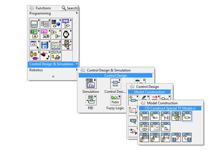
Tutorial seven Front panel tips and tricks in labview. On the Functions Palette select Control Design Simulation-Simulation-Control Simulation Loop then click and drag to size and create a Control Simulation Loop. Control and Simulation in LabVIEW The Control Simulation Loop has an Input Node upper left corner and an Output Node upper right corner.
Use the Input Node to configure simulation parameters programmatically. Visualize your application including hardware configuration measurement data debugging. Tutorial four LabView data types.
Tutorial three Using loops in labView. Create a Control Simulation Loop. Log into the system as root.
Join millions of learners from around the world already learning on Udemy. Complete the following steps to install the Control Design and Simulation Module on Linux. With the NI LabVIEW Control Design and Simulation Module you can simulate dynamic systems design sophisticated controllers and deploy your control systems to real-time hardware.
Control and Simulation in LabVIEW The Control Simulation Loop has an Input Node upper left corner and an Output Node upper right corner. When you integrate this module with the LabVIEW. The LabVIEW Control Design and Simulation Module is add-on software that integrates with the LabVIEW programming environment to offer capabilities such as built-in parallelism multicore and multirate technologies as well as tools for deploying to real-time.
However it is then necessary to first convert the model by using the CD Convert Control Design to Simulation function. A valid license for the NI LabVIEW Control Design Simulation Module from National Instruments is needed. Parameters inputs outputs must not exceed 25.
A second order system is used to introduce the use of the software for analysis and simulation of a simple system. Build powerful user interfaces for models developed in the Simulink environment and deploy them to real-time hardware with LabVIEW. Only the basic functions are demonstrated.
You can use both classical and state-space approaches to design controllers and estimators. 8 rows If you are new to the Control Design and Simulation Module consider completing the. You also can configure these parameters interactively using the Configure Simulation Parameters dialog box.
Refer to the LabVIEW Control Design User Manual for conceptual information about using the control design functionality of the Control Design and Simulation Module. Getting Started with Simulation. Control and Simulation in LabVIEW The Control Simulation Loop has an.
You also can configure these parameters interactively using the. Use the Input Node to configure simulation parameters programmatically. You can integrate measurements with design for system identification model.
However if you do not have this module it does not mean that you cannot implement a controller at all but simply not as it is proposed in this tutorial. Tutorial for LabVIEW Simulation Module 6 2 An expressive example. Overview This tutorial provides an introduction to the LabVIEW Control Design and Simulation Module and its use with the LabVIEW MathScript RT Module.
Tutorial five Using arrays in labview. Semiconductor Transportation Aerospace Defense Government. Considerations for Embedded Targets.
You can use models created in Control Design Toolkit in a Simulation diagram in the LabVIEW Simulation Module. The exported model is integrated with LabVIEW utilizing the NI External Model Interface. LabVIEW is produced by National Instruments It is assumed that you have basic knowledge about LabVIEW programming.

8 Modularizing Simulation Diagram Code Control Design And Simulation Module Labview 2018 Control Design And Simulation Module Help National Instruments
Basics Of Control Design And Simulation Ni
Types Of Simulation Subsystems Control Design And Simulation Module Labview Control Design And Simulation Module Documentation
Basics Of Control Design And Simulation Ni
2

Basics Of Control Design And Simulation Ni

Labview Control Design And Simulation 4 Configuring Up A Simulation Loop Properly Youtube
2
0 comments
Post a Comment